

I am finally reaching out as I am at my wits end and need experienced people to help me resolve my printing issue.
I have a Voxelabs Aquila (Ender 3 v2) formerly running marlin with small but manageable annoyances like overhang and manual bed leveling and thus began my journey after a year of using Aquila to start modding/upgrading the thing.
First thing i did was upgrade the fans and shroud, this improved prints slightly but was still not satisfied.
Moved to Klipper and added BLTouch and this is where all my problems started. After hours of following guides and troubleshooting of setting them both up, i still get very little bed adhesion and layers are not smooth together (gaps) with the same 3d slicing software i have been using before the switch (yes changed it to Klipper firmware in slicer)
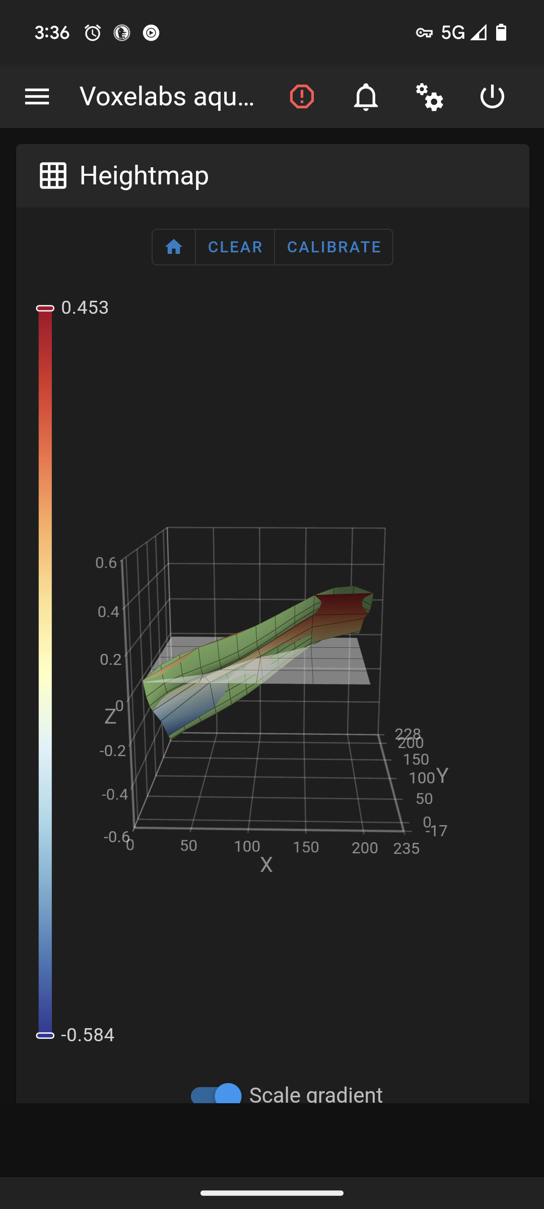
As you can see in the picture this is after a manual bed level. Where do i go from here?
Edit 2: fully cleaned nozzle, hotend, and bed without any other changes with same results.
Edit 1: forgot to add my printer.cfg
[include mainsail.cfg]

[stepper_x]
step_pin: PC2
dir_pin: PB9
enable_pin: !PC3
microsteps: 16
rotation_distance: 40
endstop_pin: ^PA5
position_endstop: 3
position_max: 235
homing_speed: 50

[stepper_y]
step_pin: PB8
dir_pin: PB7
enable_pin: !PC3
microsteps: 16
rotation_distance: 40
endstop_pin: ^PA6
position_endstop: -17
position_max: 228
position_min: -17
homing_speed: 50

[stepper_z]
step_pin: PB6
dir_pin: !PB5
enable_pin: !PC3
microsteps: 16
rotation_distance: 8
endstop_pin: probe:z_virtual_endstop
#position_endstop: 0.0
position_max: 250
position_min: -6

[extruder]
max_extrude_only_distance: 100.0
step_pin: PB4
dir_pin: PB3
enable_pin: !PC3
microsteps: 16
rotation_distance: 34.406
nozzle_diameter: 0.400
filament_diameter: 1.750
heater_pin: PA1
sensor_type: EPCOS 100K B57560G104F
sensor_pin: PC5
#control: pid
# tuned for stock hardware with 200 degree Celsius target
#pid_Kp: 21.527
#pid_Ki: 1.063
#pid_Kd: 108.982
min_temp: 0
max_temp: 250

[bltouch]
# Can't move this configuration to include because of z-offset adjustment
sensor_pin: ^PB1
control_pin: PB0
x_offset: -28
y_offset: -15
#z_offset = 0
samples: 2
speed: 2
#pin_move_time: 0.500
#probe_with_touch_mode: False
#pin_up_reports_not_triggered: True
#pin_up_touch_mode_reports_triggered: True
#stow_on_each_sample: False

[safe_z_home]
home_xy_position: 125,125 #this should be the center of your bed
speed: 50
z_hop: 10
z_hop_speed: 5

[bed_mesh]
speed: 80
horizontal_move_z: 5
mesh_min: 3, 33       #!!min and max co-ords are based on the probes location not the nozzle!!
mesh_max: 207, 213  #needs to be calibrated for your individual printer
probe_count: 5,5 #this is the number of probing points on X then Y axis
mesh_pps: 2,2
fade_start: 1
fade_end: 10
fade_target: 0

[bed_screws]
screw1: 25, 25
screw2: 195, 25
screw3: 195, 195
screw4: 25, 195

[heater_bed]
heater_pin: PA2
sensor_type: EPCOS 100K B57560G104F
sensor_pin: PC4
#control: pid
# tuned for stock hardware with 50 degree Celsius target
#pid_Kp: 54.027
#pid_Ki: 0.770
#pid_Kd: 948.182
min_temp: 0
max_temp: 130

[fan]
pin: PA0

[mcu]
serial: /dev/serial/by-id/usb-1a86_USB_Serial-if00-port0
restart_method: command

[printer]
kinematics: cartesian
max_velocity: 300
max_accel: 3000
max_z_velocity: 5
max_z_accel: 100

#*# <---------------------- SAVE_CONFIG ---------------------->
#*# DO NOT EDIT THIS BLOCK OR BELOW. The contents are auto-generated.
#*#
#*# [extruder]
#*# control = pid
#*# pid_kp = 31.251
#*# pid_ki = 2.510
#*# pid_kd = 97.268
#*#
#*# [heater_bed]
#*# control = pid
#*# pid_kp = 69.577
#*# pid_ki = 1.022
#*# pid_kd = 1184.541
#*#
#*# [bltouch]
#*# z_offset = 3.609
You must log in or register to comment.
I’ve got a Frankender myself and have been using Klipper for a few years.
I’ve been where you are and I understand the frustration.
I’m assuming your range is high enough to warrant it. The scale of the height map can be deceiving. For example my Frankender is relatively well tuned now and its range (with the not so flat stock bed) when the bed is heated is about 0.09. That’s quite a bit less than a layer height and so it’s not an issue. Could be you’re in the same boat.
So let’s take a step back and look at it fresh.
- Physical
- Kinematics
- Adjustments and corrections.
1a. Let’s make sure your gantry is square.
I’ll list them here but you can find slot of this in this video
-
loosen and then gently tighten the screws. Really just “snug” is good. Over tightening cannot only strip the aluminum threads but also “twist” the extrusion subtly (this one took me a week to find)
-
use a square (even a carpenters square if it’s all you have) and make sure that the Z extrusions are square with the X direction extrusions they mount to. If they’re not loosen the appropriate screws and, if needed, use small flat folds of aluminum foil to get them right)
-
Make sure your Z extrusions are parallel and not rotated compared to each other. Use something rigid and square (such as the X gantry extrusion if it’s undone) to align their faces.
And, while you’re at it, if the X extrusion is off anyway go ahead and find a flat reference surface (granite countertop, glass top range… carefully on this one) and make sure it’s not twisted (see more here https://youtu.be/qju5RECjVUM)
-
Make sure your actual Z gantry isn’t diverging/leaning inwards as it gains height (if you use a Squarish rule and put it on your X gantry as you slowly move it up and check that the distance is relatively the same. Won’t be perfect hit shouldn’t be obviously wrong. Again loosen the screws and then tighten them with a little more “snug” on the inner or outer set of screws to align them. You’ll probably have to loosen the top mount screws to give them room to move and then gently snug them.
-
Make sure the X gantry is parallel with the top frame. Bring it up and then make sure it’s consistently the same distance on the left and right. If not then adjust the screws on the mounting brackets that ride on the Z extrusions and get it close. Then, again, gently tighten them just past snug. Too much here and you can introduce the twisting I mentioned above… that one cost me a week once and is the reason I know about skew_compensation. Of course once loosened the issue was fixed and thankfully wasn’t something with the frame.
-
Make sure the Y gantry is also straight (to lessen XY skew) as much as possible by checking that the distance between it and the two size extrusions the Z’s mount to are relatively parallel. Loosen the 4 screws beneath the printer, straighten it and tighten… again just past snug.
1b. That covers the frame. Now for the physical motion.
- Adjust the wheel tension. If the wheel adjustment nuts are too tight you’ll get binding, flat parts, etc causing issues.
Can see an overview of this here
You’ll loosen them on the Y gantry first. Then tighten them so that, while you hold the bed with one hand, you can barely turn them with your other. If they turn easily tighten. If you can’t turn them without the bed moving… then loosen. They should barely turn with some resistance. When your done the bed should move freely but not “rock” or “pivot”
-
Now do the same for the X gantry. And you’re looking for the same results and likewise your X gantry should move freely but not “rock”.
-
Now do your Z wheels. Same as above.
-
Now for the belts. Too tight and they’ll wear out or break and strain your steppers. Too loose and you won’t get consistent movement.
There’s apps that you can use to pluck them and get them just right but I find the following works pretty well.
First the Y. Move the bed all the way back to the end stop and then “pluck” the belt on top. You want it to feel like it’s firm. Not a high pitch tone or a lot of resistant. More like your dangling an apple at the other end and you can feel the resistance. If it’s really loose or a low “thud” then tighten them.
Now do the X, move the X carriage all the way to the left and on the other side, on the bottom, do the same feeling for the same result.
1c. The bed tramming. Tighten all the screws all the way so that the bed is pulled low. Then rotate them back 2 full turns (e.g. looking from the top of the bed you’re going to turn them all 2 hours counter clock wise)
This will be done cold, you don’t need to hear the bed or nozzle. The BLTouch will handle the difference with expansion and you’ll have to adjust Z offset later. Right now what we want is your X gantry and carriage to be as close to parallel with your bed as possible. The X carriage isn’t going to be perfectly parallel with the ground, etc. but as long as the bed “matches” any tilt then it doesn’t matter. That’s what we’re tramming it for.
Now home your printer so that the motors are all engaged and using the UI move the toolhead just over the back left screw (where the bed wire retention assembly is). This is the screw you have less room to work with so I find it easier to make it my reference point.
Now using a piece of paper, a feeler gauge, anything consistent baby step the nozzle down until you just barely feel resistance. Then move it consistently up something like 5mm. Then move it over the opposite screw (the front right one). Then move the head down by 1mm 5 times. Basically we just want to be careful not to crash the head. If it’s obviously more than 5mm above then you can just move by 5.
So to recap we’ve positioned it at the reference screw touching the bed. This screw we’re not turning. Just bringing the nozzle to it. Then move the nozzle Z up 5, moved it over to a new screw, and then Z down by 5.
Now adjust the screw under front right of the bed bringing it up to the nozzle while testing with the paper/feeler and just when you feel like there’s some grab to it stop. If there’s too much then just tighten the screw until it’s right.
Now move up Z by 5mm, then move to the upper right screw and, just as before, bring it down by 5mm and adjust the screw until it touches the nozzle.
And do the same for the lower left screw.
Now home everything again… as we adjusted the screws the bed was pivoting ever so slightly… so we’ll do it again to fine tune the points.
Move over to the upper left, bring the nozzle down until you get the right resistance on the paper/feeler. Move up by 5, move to the front right screw, down by 5 and tweak the screws to match. Then do the same for the back right and front left screws. You should just about be trammed and you’ll find, as your doing this, that you don’t have to really adjust the screws much as it should already be about right as your “dialing it in”
So now you have a pretty good foundation for the next steps. Your physical printer is relatively square, things aren’t so tight that they’re twisting everything by a degree, but are tight enough to stay relatively where they should, The X Gantry is relatively parallel to its frame, and bed is relatively in line with the X gantry. Your belts are tight enough to reliably move the printer components without causing any issues. And your wheels are holding onto the extrusions so that your bed and X carriage aren’t twisting throwing off distances and skewing probes. But aren’t so tight that they deformed causing bumps and shifts as they move
Continued next reply
